We went into the design process with the goal of creating a simplistic, low-cost, robust, and manufacturable quadrotor platform. The general design consists of three major components, the motor nodes, the support rods, and the central node. It was essential that the design be reconfigurable, thus a multiple node schematic was followed which allowed for an extent of modularity that enables us to potentially adapt the quadrotor to multiple roles. With this in mind, no part of the quadrotor is glued together (.....yet, as we have not found any significant structural issues, though it is possible that the high frequency vibrations induced by the motor/rotor might reveal a need for gluing). Additionally, we have attempted to utilize electrical connectors over soldering, at a slight weight cost.
Below are photos of our SolidWorks model and of the design process. In the SolidWorks model the rotors are represented as clear cylinders.
SolidWorks-Looking down and Iso views:

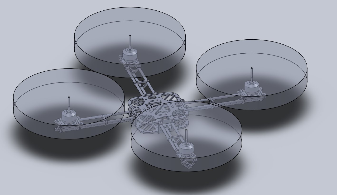
As referenced above; A, B and C represent a motor node, the support rods, and the central node respectively. One might note that the central node consists of two layers; this facilitates component placement. Following images will show the configuration of components.
Materials:
With regards to materials, the motor nodes and central node are cut out of 1/8 [in] Acrylonitrile Butadiene Styrene (ABS), while the support rods are 3/8 [in] hollow aluminium. Additionally, a number of 3[mm] steel screws are used for fixing the motor nodes and central nodes to the rods, and for fixing the motors and boards to the nodes. We felt that the aforementioned materials allowed for rapid assembly while maintaining a reasonable overall weight. This was confirmed by our overall frame mass which was about 130 grams. Improvements in the use of materials will be noted in the 'comments' section.
Assembly:
Assembly proved quite rapid and easy. A few iterations for finding the optimal hole sizing for the node->rod interface were necessary, but meticulous modeling ensured that the majority of our parts fit well. It was apparent that the rods would have to overlap in some way, which we solved by crimping the rods at intersection points. Holding the nodes in place was accomplished through the use of screws that pressed down on the rods, providing a surprisingly robust fix. If one watches carefully during the thrust testing video they will see a nut fall off of a screw, while this was not an issue during the test since each screw had an additional redundant nut, we decided to eliminate such uncertainty in our quadrotor by tapping the ABS. The ABS to screw friction combined with the dampening that the ABS provides should keep the screws from rotating during operation.
A motor attached to a motor node:

Close up of the Center Node:

Central Node Configuration:
The slots in the central node house the ESCs for our brushless motors (A2208-14). Wires from the ESCs are routed through the openings at the top of the node through those between the rods out to the motors. The battery is placed on the bottom of the central node, and the 'ping' sensor (our current altimeter, at least until we get our barometer output working properly) will be placed under the node as well. Our Control, IMU, and wireless boards are configured to be placed between the ESCs on the top of the central node.
The Frame with ESCs, Battery, and Motors incorporated:

Central Node with ESCs, Battery, Control Board:

Comments:
We believe that the current frame will prove sufficient for our purposes. It is light, sturdy, easy to construct, and capable of housing the components we require, yet we feel that when we have more time improvements are possible. Wiring up the quadrotor has made us realize that more consideration of wire routing might prove beneficial during the modeling process. Moreover, our nodes seem more robust than necessary and we could probably stay within our design goal of robustness while reducing mass of material used. In the future, use of carbon fiber tubing and sheets, and perhaps even thermoplastics might allow for an equally functional structure that is lighter and more aesthetically pleasing.
Overall though, considering that we designed and assembled the quadrotor over a weekend and accomplished the majority of the wiring in a day (some wiring was on hold while we waited for the appropriate connectors), we are quite happy with our results. And we must admit, this is one cool looking quadrotor.


